


Detailed Explanation about the Chips
Regular chips
1.1 Start Chip: Start Chip
1.2 DC Motor Chip : DC Motor Chip
1.3 Servo Chip : Servo Motor Chip
1.4 Voice Chip: Voice Chip
1.5 Dot Matrix Chip : Dot Matrix Chip
1.6 On Chip: Port Opening Chip
1.7 Off Chip: Port Closing Chip
1.8 Variable Chip: Variable Chip
1.9 Calculate Chip: Calculate Chip
Delay : Delay management chip
2.1 Delay Chip: Delay Chip
While : Repetition related chips
3.1 While Chip: Repeated Chip
3.2 Break Chip: Repeated Stop Chip
3.3 Loop Chip: Circular Chip
If Else : Conditions related chip
4.1 If Else Chip: Condition Chip
4.2 IR Remote Control 5 Chip: 5 button infrared remote control chip
4.3 IR Remote Control 8 Chip: 8-Burton Infrared Remote Control Chip
4.4 Bluetooth R/C 10 Chip: 10 button Bluetooth remote control chip
4.5 Bluetooth R/C 12 Chip: 12- Button Bluetooth Remote Chip
4.6 Contact S/W Chip: Access Switch Chip
4.7 Rand Chip: Random Chip
Sensors: Sensor-related chips
5.1 IR Sensor Chip: Infrared Sensor Chip
5.2 Magnetic Chip: Magnetic Sensor Chip
5.3 PIR Sensor Chip: Human Body Sensors Chip
5.4 Tilt Sensor Chip: Tilt Sensor Chip
5.5 Color Sensor Chip: Color Sensor Chip
5.6 Color Sensor (New) Chip: Color Sensor (New) Chip
Function Chip: a function-related chip
6.1 New Function Chip: Creating a New Function
▶Regular Chips
_____________________________________________________________
1.1 Start Chip

Main Function
-Chip that indicates the start of a program
Specific Explanation
-There is no option, and it is fixed to the program screen by default.
-The user starts programming the chip by placing other chips under the starting chip.
Caution
-The starting chip will not be moved.
1.2 DC Motor Chip
Main Function
-A chip that decides speed and direction of the DC Motor
Specific Explanation
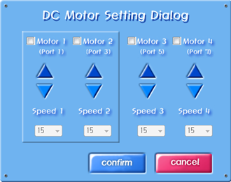
-Press the option button on the DC motor chip to display the DC motor setup dialog box as follows.
How to use the Chatbox
-When the DC motor chip is set, the robot's DC motor moves as set until the next DC motor chip is released.
-To specify how long the set DC motor will move, typically place a delay chip after the DC motor chip.
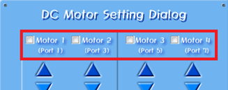
-In the Port Selection area, you can select the port to which the motor is connected by selecting the check box.

-The direction selection area allows you to select the rotation direction of the motor using the triangle icon.
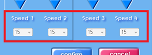
-The speed selection area allows you to select the operating speed of the motor. The speed can be set from 0 to 15, where 0 represents a stop..
Example
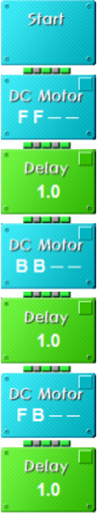
1. The motor operates only when the direction and speed of the DC motor are set and the delay chip is used to allow time for the motor to move.
2. The motor does not stop automatically after the operation time has elapsed, so a DC motor chip with zero speed must be inserted to stop the motor. The example below shows how the motor changes in the direction of rotation every one second.
1.3 Servo Chip

Key Features
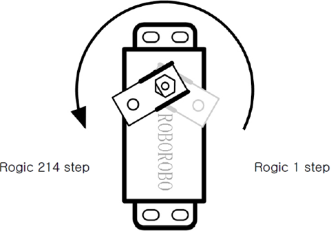
-It is a chip that moves the servo motor. The servo motor is designed to move by a given angle, and it can split 220 movements into numbers from a minimum of 1 to a maximum of 214, providing detailed settings.
Detailed description
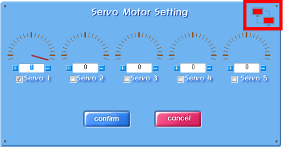
-Press the option button on the servo motor chip to display the DC Motor Settings dialog box as follows.
dialog box and usage description

-If you check and activate the servo motor on the corresponding output port among the numbers Servo 1 through 5, you can display the scale.
-The semicircular scales represent the servomotor's moving radius, which allows you to click the scale using your mouse or enter a value directly.
precautions
-The triangular grooves on the servo motor shaft (the dents on the white motor shaft) indicate the reference points (zero) on the servo motor.
-The radius of movement of the servo motor is 220 degrees, so 107 steps of the servo motor chip is 90 degrees as shown below.

A sufficient amount of time (approximately 1 second) is required to set the desired angle on the servo motor chip and then move to the target angle.
If the program is made using only the servo motor chip, the servo motor shaft will not reach the target angle and will take the next action.
Reference
-The radius of movement of the servomotor:
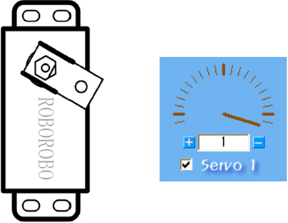
-To set the starting point for the servo motor:
Plug the connecting parts into the axis of the servo motor and turn right to the end.
Pull out the connected parts and match the starting point (1 step) as the operating reference.
In the logic program, set the servomotor chip to one step and download it,
By operating the robot, you can see that the servo motor shaft moves to the starting point.
-Real-time movement:
You can connect communication to move the selected servo motor in real-time.
Select the moving servo motor and press the connect button in the upper right corner.
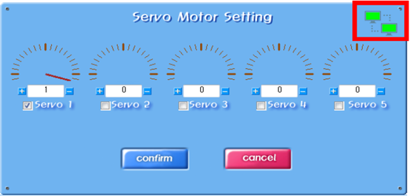
After confirming that the button has been changed to the connected state, you can confirm that the servo motor is moving by changing the value of the selected motor.
1.4 Voice Chip

Key Features
-This chip activates the Voiceboard
Specific Explanation
-The voice chip exports an output signal that operates the voice board to the output port that you set.
-When you press the option button on the voice chip, the voice setting dialog box appears as follows.
How to use the Voicebox

-The voiceboard must be connected to one of the robot's output ports (PORT1 to PORT5) and you can select the port to be connected in the voice setting dialog box.
1.5 Dot Matrix Chip

Key Features
-This chip activates the Dot Maxtrix Board
Specific Explanation
-Dot matrix chips are responsible for printing letters, numbers, symbols, and images on the dot matrix board.
-The output of the dot matrix board is largely divided into character mode and image mode, which outputs alphabets, numbers, and symbols, and image mode freely draws and outputs images beyond the fixed character mode.
-Click the options button located in the upper right corner of the dot matrix chip to display the dot matrix board settings dialog as follows
How to use the Chatbox

-Specific Explanation
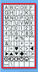
-a table where you can enter letters, numbers, and symbols
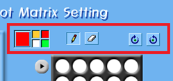
Color Selection Area, Rotation Button
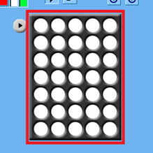
Display screen
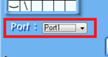
Output Port Settings
-How to Use

If you select green in the color selection area and press A in the table, A is displayed on the display screen.
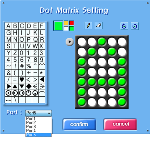
After that, if you specify an output port to which the dot matrix board is connected, a program chip with a green character A output to that port is completed.
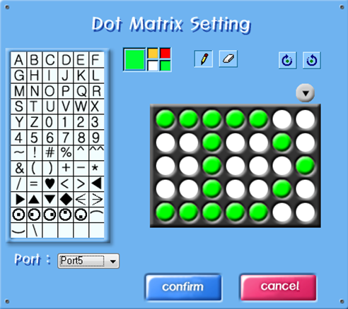
The figure you enter can rotate 90 degrees. The figure above shows the result of rotating 90 degrees clockwise.
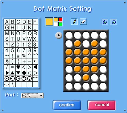
The table stores letter, number, and symbol information, so you can select the color you want and select the contents of the table.
The picture above shows the result of selecting orange and entering the symbol Heart (♥).
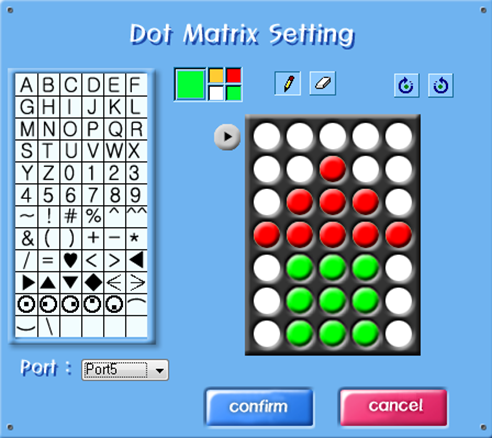
It can be drawn and displayed directly, as well as in the form stored in the table. Unlike in character mode, where fixed characters are entered through a table, in image mode, you can draw any shape on the display screen by combining colors. The example above is the shape of a house with red and green colors.
Caution
-When setting up a dot matrix chip, be sure to select the output port to which the dot matrix board is connected.
-And if you want to keep changing the output when using the dot matrix board, you need to give the delay for at least 0.6 seconds to work correctly.
1.6 On Chip

Key Features
-It is a chip that turns on the LED or buzzer.
Specific Explanation
-Used when an LED or buzzer connected to the CPU board is turned on by the program.
-When you press the option button on the port opening chip, the port opening dialog box appears as follows.
How to use the Chatbox
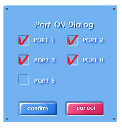
-The port opening dialog box represents the robot's output ports (PORT1 to PORT5)
-There are five check buttons.
-If four LEDs are connected from output ports 1 to 4, to operate the LEDs
-You must check port 1, port 2, port 3, port 4.
Cautions
-The port opening chip should always be used with the port closing chip.
-If you opened the port and used it, closing the port is the correct way to program the chip.
1.7 On Chip

Key Features
The chip that turns off the LED or the Buzzer.
Specific Explanation
-Used to turn off an LED or buzzer connected to the CPU board by a program.
-When you press the option button on the port opening chip, the port opening dialog box appears as follows.
How to use the Chatbox
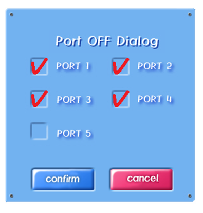
-The Port Close dialog box has five check buttons indicating the robot's output ports (PORT1 to PORT5).
-If four LEDs are connected from output ports 1 to 4, port 1, port 2, port 3, and port 4 must be checked to turn off the LEDs.
Caution
-The port close chip should always be used with the port open chip.
-If you opened the port and used it, closing the port is the correct way to program the chip.
Example

If the LED is not turned off after it is turned on, it will remain on.
The example on the left is an example of turning on the LEDs in ports 1 and 2 and holding them for 1 second, turning off the LEDs in ports 1 and 2, and turning on the LEDs in ports 3 and 4 for 1 second and then turning off,
The example on the right is an example of turning on the LEDs on ports 1 and 2 and holding them for 1 second, and then turning on the LEDs on ports 3 and 4.
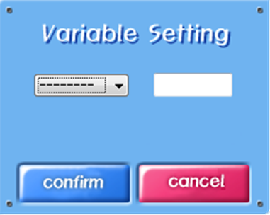
1.8 Variable Chip

Key Features
-A chip that creates a new variable and sets an initial value, or sets a new value for an existing variable.
Specific Explanations
-A variable is a number whose value changes and can be changed by the program.
-A maximum of 16 variables can be used in logic.
-The user can use variables to store the data received from the sensor.
-Variables are created, initialized, and changed by variable chips and calculation chips, and condition chips and repetition chips
-They're compared, so to use variables, you can use variable chips, computational chips, conditional chips, repetitive chips
-You need to know how to use it.
-Click the option button located in the upper right corner of the variable chip to set the variable as follows
-The dialog appears.
How to Use the Chatbox
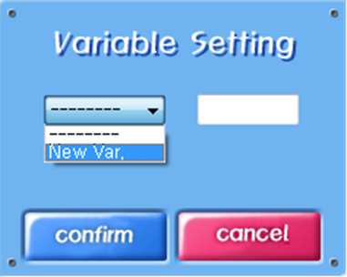
First, select the Combo box to generate a variable, then select Create a new variable (New Var.).
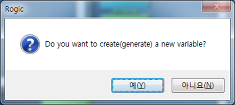
A dialog box appears asking if you want to create a new variable.
Click the Yes button.


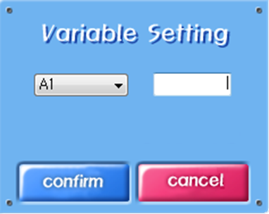
In New Name, enter the name of the variable you want to use.
Variable names can be up to two characters, only alphabetic and numeric characters.
Type a variable name and click Confirm
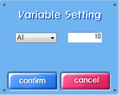
The part that sets the initial value of the variable.
Enter the initial value of the variable to be created, and then click Confirm.

An A1 variable with an initial value of 10 was created.
The conditional chip or repeat chip attached under this variable chip can be compared/judged/repeated using variable A1.
Caution
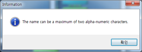
Variable names can be up to two characters, only English characters and numbers. If you enter a variable name of more than three characters, the above warning appears.
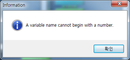
The first letter of a variable name must start with an English letter. If you start with a number, you'll see the above warning.
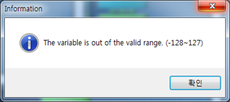
Variables can only be integers; variables can also be entered from -128 to 127.
1.9 Calculate Chip

Key Features
-It's a chip that calculates variables and variables and variables and variables and constants
Specific Explanations
-A computational chip is a chip that adds, subtracts, multiplies, and divides variables and constants generated by variable chips.
-If you click the options button located in the upper right corner of the calculation chip, the calculation chip settings dialog appears as follows.
How to use the Chatbox
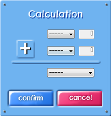
The user can specify two operands and an operator and a variable to store the results of the Gricho operation.
The operand can choose either a variable or a constant (normal number); the following example uses an A1, AD variable that has already been created.

If a variable is created, the variable appears in the list of operands as above.
If you select A1 or AD, the variable is selected as operand, and if you select Value, the constant is selected as operand. If you select a constant, you must enter the constant value you want to calculate next to the operand.
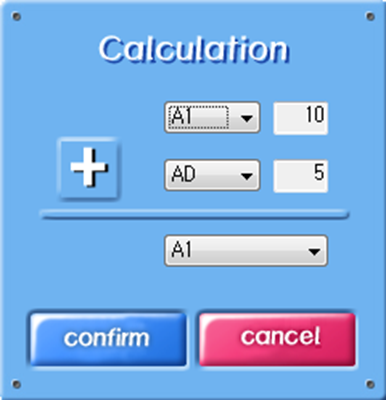

The figure above is an example of storing the value of variable A1 plus the value of variable AD in variable A1.
If 10 was stored in A1 and 5 in AD, the calculation result would be 15 in A1.


When you click an operator, the addition (+) operation changes to the subtraction (-) operation.
If 10 was stored in A1 and 5 in AD, the calculation result would be stored in A1.


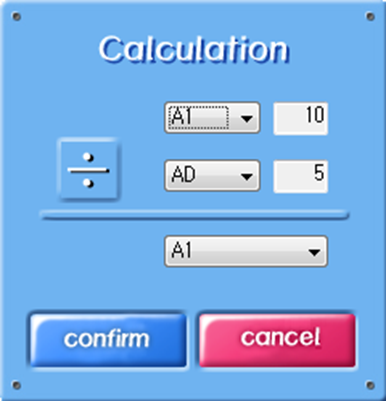

If you keep clicking on the operator, you can also perform multiplication and division.
If there were 10 in A1 and 5 in AD, the multiplication result would be 50 in A1 and the division result would be 2 in A1.

In addition, you can perform arithmetic operations using only one variable.
Caution

Variables can only be integers; variables can also be entered from -128 to 127.
As a result, special care should be taken to ensure that the operation results of the variables do not exceed the input range.
▶Delay
_____________________________________________________________
2.1 Delay Chip
Key Features
-A chip that delays the status for a specified time.
Specific Explanations
-Proper delay is required to operate the robot.
-A delay chip is a chip used to delay a robot's condition for a certain period of time.
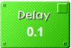
-Press the option button on the delay chip to display the delay setting dialog box as follows.
How to use the Chatbox
The unit is 0.1 seconds, with a delay of 0.1 to 25 seconds.
There are two methods of typing on the keyboard and one method of typing on the increase and decrease buttons.
▶While
_____________________________________________________________
3.1 While Chip
Key Features
-It is a chip that repeats a particular chip.
Specific Explanations
-Robots will perform a lot of simple repetitive tasks.
-Repetition chips are chips used to perform these iterations, which repeat normal chips placed between the chip () indicating the beginning of the repetition and the chip (
) indicating the end of the repetition.
How to use the Chatbox
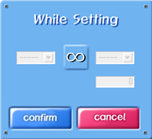

-Repeated chips have infinite repetition mode and condition repetition mode.
The mode of the repeat chip can be set by pressing the option button.
-If you set it to '∞' as shown in the picture on the left below, the repeat chip will be set to infinite repeat mode
The chips placed between the repeating chips are repeated indefinitely.
-If the condition is set as shown in the right side below, it is set to the condition repetition mode and only when the condition is true
You repeat the chip placed between the repeat chips.
Caution
-If you use a repeating chip in infinite repetition mode, you will repeat it indefinitely unless you use the repeating stop chip to escape.
-At this time, the chips underneath the repeat chip are not executed
Example

This program is configured to allow the robot to advance indefinitely by repeating the command chip advancing for 0.1 seconds.
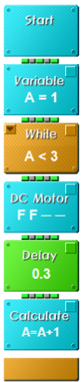

Example of using a repeat chip with a variable chip.
Each time A repeats the while statement, it increases by 1 through the calculation chip, so the DC motor operates on the first and second iterations and repeats until the third iteration is performed before the program is terminated.
3.2 Break Chip

Key Features
-It's a chip that stops repeating.
Specific Explanations
-If you encounter a repeat stop chip inside the repeat chip, it stops repeating and exits the repeat chip.
Caution
-Repeated interruption chips must be used inside the repeat chip.
Example

This is an example of a recurring chip, which performs a sensor check inside the recurring chip and exits the recurring chip if the result is true.
3.3 Loop Chip

Key Features
-A chip that circulates a specified number of times.
Specific Explanations
-A repeat chip is used for infinite repetition or condition repetition using a variable. However, in order to repeat a condition by repeating a condition on a repeat chip a set number of times, it must go through a complicated process such as defining, initializing, calculating, and comparing conditions.
-A Loop Chip is a chip that simplifies this complex process and repeats the regular chips placed between the chip ( ) representing the beginning of the cycle and the chip (
 ) representing the end of the cycle.
-The number of repetitions of a circular chip can be set by pressing the option button as shown below. Below is an example of a chip placed between circular chips set to repeat three times
How to use the Chatbox

Caution
-Loop Count can be from 0 to 127.
Example

This is an example in which 1 forward second and 1 backward second are operated three times.
▶If Else
_____________________________________________________________
4.1 If Else Chip


Key Features
-Compare input port values or conditions and run the programmed chip according to the result.
Specific Explanations
-The robot needs a sensor to respond to the external environment. In other words, it uses a condition chip to allow the robot to perform different actions depending on the sensor value. When you press the option button on the condition chip, the conditioning dialog box (If Setting) appears as follows.
How to use the Chatbox


-If 'Sensor Port' is checked, the chips placed on each YES and NO are executed according to the input port value, and if 'Compare' is checked, the chips placed on each YES and NO are executed according to the conditions.
Example

A simple example of a condition chip.
If the value of the sensor connected to input port 1 is true, the left wheel will reverse for one second, and if the value of the sensor is false, both wheels will move forward.

This is an example with a condition chip and a variable chip. Loop will be turned 4 times and the value A will be increased by 1 through the calculate after if.
The setting of if is set to A==2, so only if A and 2 are the same, the DC motor goes to Yes and the DC motor goes to No and stops otherwise.
4.2 IR Remote Control 5 Chip

Key Features
-It is a chip that executes the command of the infrared wireless remote control.
Specific Explanations
-The 5-button infrared remote control chip is a chip that can specify the action to be taken when the switch on the remote control transmitter (the part where the user sends commands to the robot) is pressed. Pressing the option button on the remote control chip will display the Remote Control Key Setting dialog box as follows.
How to use the Chatbox


-The remote control key setting dialog box shows the remote control transmitter. Here, the user must press the key to be processed and specify the input port (IN) to which the remote control receiver is connected. For example, if the remote control receiver is connected to the robot's CPU board input port 7 and button 1 is pressed, set the port of the remote control key setting dialog box to Port 7, press button 1, and then click [confirm]. Then, if remote control number 1 is pressed, the chip to be executed can be used by placing it between the remote control chips.
-The infrared remote control receiver mainly uses input port 7, so the default value is Port7. The 5-button infrared remote control chip can handle more than one key combination. If you want to handle when 1 and 3 of the remote control are pressed together, press 1 and 3 on the remote control chip and put the chip to be processed between the remote control chips.
Caution
-The five-button infrared remote control chip must be used with a repeat chip because it requires continuous inspection of commands sent by the user.
Example

5 button This is an example of an infrared remote control chip. When button 1 is pressed from the remote control, the robot moves forward, and when button 2 is pressed, the robot moves backward. The stop command between the remote control chip and the repeating chip is to stop when the remote control signal does not come in.
4.3 IR Remote Control 8 Chip

Key Features
-It is a chip that executes the command of the infrared wireless remote control.
Specific Explanations
-The 8-button infrared remote control chip is a chip that can specify the action to be performed when the switch on the remote control transmitter (the part where the user sends the command to the robot) is pressed. Pressing the option button on the remote control chip will display the Remote Control Key Setting dialog box as follows.
How to use the Chatbox


-A remote control transmitter with eight buttons appears. The function is the same as that of the 5-button remote control chip, but the number of buttons varies. Press the key to be processed and specify the input port (IN) connected to the remote control receiver. For example, if the remote control receiver is connected to CPU board input port 7 of the robot and button 1 is pressed, set the port of the remote control key setting dialog to port 7, press button 1, and then click [confirm]. Then, use the chip to be executed when remote control number 1 is pressed between the remote control chips.
-The 8-button remote control chip can handle up to 2 button key combinations, with one button on each side. If you want to create a key combination of two buttons, you have to select one of the 1st to 4th buttons and one of the 5th to 8th buttons. For example, if you want to process when the 1st and 5th of the remote control are pressed together, press 1 and 5th on the remote control chip and put the chip to be processed between the remote control chips.
cautions
-The 8-button infrared remote control chip must be used with a repeat chip because it requires continuous inspection of commands sent by the user.
Example

8 Button This is an example of an infrared remote control chip. When buttons 1 and 5 are both pressed from the remote control, the robot moves forward, and when buttons 2 and 6 are pressed, the robot moves backward. The stop command between the remote control chip and the repeating chip is to stop when the remote control signal does not come in.
4.4 Bluetooth R/C 10 Chip

Key Features
-It is a chip that executes the command of the Bluetooth wireless remote control.
Specific Explanations
-The 10 button Bluetooth remote control chip is a chip that can specify the action to be performed when the switch on the remote control transmitter (the part where the user sends the command to the robot) is pressed. Press the option button on the remote control chip to display the Remote Control Key Setting dialog box as follows.
How to use the Chatbox


-The Remote Control Key Settings dialog box shows the remote control transmitter. There are a total of 10 buttons. Here, the user specifies the key to be processed. For example, if button 1 is pressed, press button 1 and then click [confirm] .
-Then use the chip to be executed when button 1 is pressed between the remote control chips.
-It can also handle two key combinations. It can handle when one of buttons L, 1 to 4, and one of buttons R, 5 to 8, are pressed.
Caution
-The 10 button Bluetooth remote control chip must be used with a repeat chip because it is necessary to continually inspect the commands sent by the user.
Example

10 button This is an example of a Bluetooth remote controller chip. When button 1 of the remote control is pressed, both motors rotate forward and the robot moves forward. When the remote control signal does not come on, it stops by a stop command between the remote control chip and the repeating chip.
4.5 Bluetooth R/C 12 Chip

Key Features
-It is a chip that executes the command of the Bluetooth wireless remote control.
Specific Explanations
-The 12-Button Bluetooth remote control chip is a chip that can specify the action to be taken when the switch on the remote control transmitter (the part where the user sends commands to the robot) is pressed. Pressing the option button on the remote control chip will display the Remote Control Key Setting dialog box as follows.
How to use the Chatbox
-It can also handle two key combinations. It can handle when one of the L1, L2, and arrow buttons and one of the R1, R2, E, X, O, and V buttons are pressed.
-The Remote Control Key Settings dialog box shows the remote control transmitter. There are a total of 12 buttons. Here, the user specifies the key to be processed. For example, if the ▲ button is pressed, press the ▲ button, and then click [confirm]. Then, if the remote ▲ button is pressed, the chip to be executed is used between the remote control chips.
Caution
-The 12 button Bluetooth remote control chip must be used with a repeat chip because it is necessary to continually inspect the commands sent by the user.
Example

This is an example of a 12 Button Bluetooth remote controller chip. When the ▶ button is pressed from the remote control, the left motor rotates forward, and the robot makes a right turn. When the remote control signal does not come on, it stops by a stop command placed between the remote control chip and the repeating chip.
4.6 Contact S/W Chip

Key Features
-If the state of the contact switch matches the state you set, run the programmed chip.
Specific Explanations
-A contact switch chip is a chip that can specify a specific operation according to the state in which the switch on the contact switchboard is pressed. By pressing the option button on the contact switch chip, you can specify the input port to which the contact switchboard is connected and the state of the switch you want to process as follows.
How to use the Chatbox

--The contact switch chip verifies that the status of the input port designated as the Sensor Port is ON (if the switch is pressed) or OFF (if the switch is not pressed), and then runs the chip placed inside the contact switch chip only when the condition is true. After running all the internal chips, read the sensor port value again to determine the true-false condition. Therefore, as long as the condition is met, the contact switch chip and its internal chips will continue to run.
Caution
-The contact switch chip is mainly executed when receiving external input, so it is located inside the while chip to continuously inspect the input port.
Example

A simple example of a contact switch chip. If the state of the contact switch connected to input port 1 is ON, both motors will rotate forward and the robot will move forward. If the state is OFF, stop.
4.7 Rand Chip

Key Features
-Randomly output the signal to output ports 1 to 4 and execute the programmed chip when the signal is input to the input port of the same number as the output port.
Specific Explanations
-If you set the delay by pressing the option button on the random chip, the signal is sent to one of the output ports 1 to 4 in a cycle of delay. If you set the delay to 1 second and connect the LED to the output ports 1 to 4, one of the four LEDs will turn on every second. When the signal comes in from the input port of the same number as the output port where the LED is turned on, the contents of the normal chip in the Landup chip are performed.
Caution
-In order to carry out the chip program in the random chip, a contact sensor or infrared sensor must be connected to the input ports 1 to 4 and input according to the output.
-Random chips are executed when receiving external inputs, so you must constantly inspect the input ports using the While Chip.
Example

This is an example of using a random chip. If the LED is connected to the output ports 1 to 4 and the contact sensor is connected to the input ports 1 to 4, the LED lights up randomly every second. When the LED on output port 2 is turned on, press the contact sensor on input port 2 and it is displayed on the dot matrix board.
▶Sensors
_____________________________________________________________
5.1 IR Sensor Chip

Key Features
-Run the chip according to the status of the infrared sensor connected to the input port.
Specific Explanations
-An infrared sensor chip is a chip that can specify a specific operation depending on the detected state of the infrared sensor board. By pressing the option button on the infrared sensor chip, you can specify the input port to which the infrared sensor board is connected and the state of the sensor you want to process as follows.
How to use the Chatbox


-The infrared sensor chip verifies that the status of the input port designated as the Sensor Port is ON (if the infrared sensor is detected) or OFF (if the infrared sensor is not detected), and then runs the chip inside the infrared sensor chip only when the condition is true. After running all the internal chips, read the sensor port value again to determine the true/false condition. As long as the condition is met, the infrared sensor chip and its internal chips will continue to be executed.
Caution
-The infrared sensor chip needs to be continuously inspected for external inputs, so it should be located inside the while chip to inspect the input port.
Example

5.2 Magnetic Chip

Key Features
-Run the chip according to the state of the magnetic sensor connected to the input port.
Specific Explanations
-A magnetic sensor chip is a chip that can specify a specific operation according to the detected state of the magnetic sensor board. By pressing the option button on the magnetic sensor chip, you can specify the input port to which the magnetic sensor board is connected and the state of the sensor you want to process.
How to use the Chatbox


-The magnetic sensor chip verifies whether the status of the input port designated as the sensor port is ON (if the magnetic sensor is detected) or OFF (if the magnetic sensor is not detected), and then runs the chip inside the magnetic sensor chip only when the condition is true. After running all the internal chips, it reads the sensor port value again to determine the true/false condition. As long as the condition is met, the magnetic sensor chip and its internal chips will continue to be executed.
Caution
-The magnetic sensor chip needs to be continuously inspected for external input, so it should be located inside the while chip to inspect the input port.
Example

Here is a simple example of a magnetic sensor chip. If the state of the magnetic sensor connected to input port 1 is ON, both motors will rotate forward and the robot will move forward. If the state of the sensor is OFF, stop.
5.3 PIR Sensor Chip

Key Features
-Run the chip according to the state of the human body sensor connected to the input port.
Specific Explanations
-A human body detection sensor chip is a chip that can specify a specific operation according to the detected state of the sensor board. By pressing the option button on the human body detection sensor chip, you can specify the input port to which the human body detection sensor board is connected and the state of the sensor you want to process as follows.
How to use the Chatbox
-The human body sensor chip checks whether the status of the input port designated as the sensor port is ON (if the human body sensor is detected) or OFF (if the human body sensor is not detected), and then runs the chip placed inside the human body sensor chip only when the condition is true. After running all the internal chips, read the value of the sensor port again to determine the true/false condition. Therefore, as long as the condition is met, the human body sensor chip and the chips inside it will continue to be executed.
Caution
-Since the human body detection sensor chip needs to continuously inspect external inputs, it is located inside the while chip to inspect the input port.
Example

A simple example of a human body sensor chip. If the state of the human body sensor connected to input port 1 is ON, the LED connected to output port 1 flashes three times every 0.5 seconds, and if the sensor is not detected, output port 1 is turned off.
5.4 Tilt Sensor Chip

Key Features
-Run the chip according to the state of the tilt sensor connected to the input port.
Specific Explanations
-A tilt sensor chip is a chip that can specify a specific operation according to the detected state of the tilt sensor board. By pressing the option button on the tilt sensor chip, you can specify the input port to which the tilt sensor board is connected and the state of the sensor you want to process as follows.
How to use the Chatbox

-The tilt sensor chip verifies that the status of the input port designated as the Sensor Port is ON (if the tilt sensor is detected) or OFF (if the tilt sensor is not detected), and then runs the chip placed inside the tilt sensor chip only when the condition is true. After running all the internal chips, read the sensor port value again to determine the true/false condition. As long as the condition is met, the tilt sensor chip and its internal chips will continue to run.
Caution
-Since the tilt sensor chip needs to continuously inspect external inputs, it should be located inside the while chip to inspect the input port.
Example

Here's a simple example of a tilt sensor chip. If the tilt sensor connected to input port 1 is ON, the left motor rotates forward and the right motor rotates backward for one second. Therefore, the robot turns right in place and stops one second later.
5.5 Color Sensor Chip

Key Features
-Run the chip according to the detected color of the color sensor connected to the input port.
Specific Explanations
-A color sensor chip is a chip that can specify a specific operation depending on the color detected by the color sensor. By pressing the option button on the color sensor chip, you can specify the input port to which the color sensor board is connected and the color of the sensor you want to process as follows.
How to use the Chatbox


-The color sensor chip executes the chip placed inside the color sensor chip if the detected color of the input port designated as the Sensor Port is the same as the specified color. After all the chips inside have been executed, the sensor port's detection color is recognized again to determine the true/false condition. As long as the condition is met, the color sensor chip and the chips inside it will continue to be executed.
Caution
-Since the color sensor chip needs to be continuously inspected for external input, it should be located inside the while chip to inspect the input port.
Example

A simple example of a color sensor chip. If the color sensor connected to input port 1 continues to detect red, the LED connected to output port 1 will be turned on and off every second.
5.6 Color Sensor(New) Chip

Key Features
-Run the chip according to the detected color of the color sensor connected to the input port.
Specific Explanations
-A color sensor (New) chip is a chip that can specify a specific operation depending on whether or not the color sensor is detected. By pressing the option button on the color sensor chip, you can specify the input port to which the color sensor board is connected and the color of the sensor you want to process as follows.
How to use the Chatbox


-The Color Sensor (New) chip executes the chip placed inside the Color Sensor (New) chip if the detected color of the input port designated as the Sensor Port is the same as the specified color. After running all the internal chips, it recognizes the sensor port's detected color again to determine the true/false of the condition. Therefore, as long as the condition is met, the Color Sensor (New) chip and its internal chips will continue to be executed. Unlike the Color Sensor chip, white and black are excluded from the list.
Caution
-Since the Color Sensor (New) chip needs to continuously inspect external inputs, it should be located inside the While Chip to inspect the input port.
Example

The following is a brief example of a color sensor (New) chip. If the color sensor connected to input port 1 detects a red color, the LED connected to output port 1 turns on, and if it is no longer detected, the LED is turned off.
▶Function Chip
_____________________________________________________________
6.1 New Function Chip

Key Features
-A chip that creates a new function.
Specific Explanations
-Function means 'function, action, function' and refers to a set of chips that combine various chips in a meaningful way. If you make frequently used actions into Function, you can easily write a program by adding only the relevant Function chip without having to configure a chip one by one.
How to use the Chatbox
When you press the New Function Chip, a dialog box appears in which you enter the name of the function you want to create.

-Type a name for the function and click OK.

-If the function name is entered correctly, one empty function is created as shown above.
Caution
-The infrared sensor chip needs to be continuously inspected for external inputs, so it should be located inside the while chip to inspect the input port.
Example
We properly inserted the DC Motor and Delay chips in order to make the robot move in zigzags. This completes the ZIGZAG function.

The created function is added to the Function chip on the left. To use it, click and move the function to be used on the Function chip on the left.