


Key Components
Information on the main circuit boards included in the ROBOKIT.
CPU Board
Overview
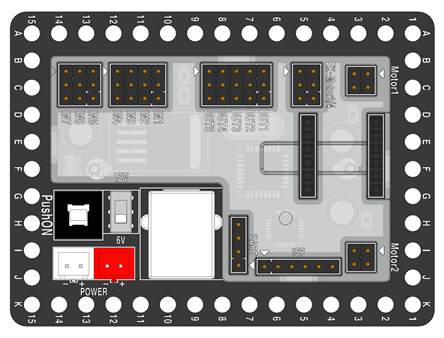
12V DC motor output (2 battery connectors)
6V ↔ 12V output change using the Voltage Slide Switch
Programming using the Rogic Program
Can control 4 DC motors simultaneously.
4-channel motor control when the external motor driver is connected
7 input ports (Using 3 sensors within ROBOKIT- Motion sensor/IR sensor/Sound sensor)
5 input ports (Using 3 output circuits- Servo Motor/LED/Single-tone Buzzer)
Program downloadable using the ISP cable
PC communication using the USB A/B Cable
Built-in USB port for downloading the Rogic Program
Product information
Model: PC0M-N016-150
Release Date: 2014-12
Manufacturer: RoboRobo
Manufactured Country: South Korea
Size / Weight: 78(L) * 58(W) * 13(H)mm / 27g
Target Age: 8+
Price: 32,000 KRW
Product Link: Official Shopping Mall
Product Specs
MCU: ATmega8A
Voltage: 6V ~ 20V (Recommended - 6V or 12V)
Electric current Consumption: 0.03A (When motor is not running)
Motor Connector: 2x (2x for upgrade)
Output Connector: 5x
Input Connector: 7x
Battery: Alkaline AA size
Size/ weight: 78(L) * 58(W) * 13(H)mm / 27g
Exterior Description

Input (IN) Port- A port that receives signals from the outside
Used to detect exterior Stimulation using the motion sensor board and the IR sensor Board.

Output (OUT) Port- Ports that supply power/signals to connected circuit components.
Connect parts such as LED boards and buzzer boards and use them to send control signals

DC Motor Extension Port- Used when separate DC Motor Drive board is utilized

Motor Port- Used to send control signals and provide power using the DC motor.
Connect the black cable connected to the DC motor to the port that is next to the white triangle.

Motor Drive Port - Designated port for the DC motor Drive Board connection.
Must be connected according to the DC motor drive board’s direction for proper use.

USB Connection Port- Designated port for USB cable connection.
Connect the cable to send programs written from the PC to the CPU board.

Voltage switch- It is a switch that adjusts the output to 6V or 12V depending on the battery voltage applied to the CPU board.
Selectively operate based on the number of dedicated battery cases connected to the CPU board

Battery case connection port- Port used to connect designated battery case’s cable
It is advised to use a 6V only battery case that is included in the Robot and Program.

Power Switch- A switch that allows the CPU board to be powered on and off.
It can be used when power is applied through the battery case.

Assembly Holes - It is a dedicated hole that can be assembled with the PCB frame using bolts/nuts provided within ROBOKIT.
Caution
Never put parts in your mouth.
Do not throw or swing parts or products at people.
Be careful with handling sharp parts
Keep parts away from the fire.
Semiconductors, motors, and electronic components may not work if they come into contact with water or get wet.
Do not use different types of batteries mixed together.
Assemble and operate under the supervision of a guardian or teacher.
It contains small parts, so it cannot be used by children under the age of three.
Motor Drive Board
Overview

The motor drive board controls the DC motor that moves the robot.
Depending on the CPU board’s signal, the rotation direction and speed of the DC motor can be adjusted.
Product information
Model: PC0D-N010-150
Manufacturer: RoboRobo
Manufactured Country: South Korea
Target Age: 8+
Price: 8,000 KRW
Product Link: Official Shopping Mall
How to use


Connect to the CPU board’s motor drive port to use
Must be connected according to the direction of the DC motor drive board for proper operation.
Product Specs
MCU: ATmega8A
Input Voltage: 6 ~ 12V (Max 18V)
Electric current Consumption: 1.8A
Motor: DC Motor 2x (Max 4)
Other: DC motor can be operated through year 2015 12 V School kit CPU board
Caution
1. Never put parts in your mouth.
2. Do not apply excessive force to the movable part or various parts.
3. Do not put your finger in the assembly or moving part.
4. Do not throw or swing parts or products at people.
5. Be careful with handling sharp parts of parts or products.
6. Keep parts away from the fire.
7. Be careful that semiconductors, motors, and electronic parts may not operate if they come into contact with water or get wet.
8. Batteries may leak and rupture, so put (+)(-) properly.
9. Do not charge, disassemble, short-circuit, or heat the battery.
10. Do not use batteries of different types or mixed with used batteries.
11. When liquid flowing out of the battery enters your eyes, wash it with water immediately and go to a nearby hospital.
12. Wash liquid flowing out of the battery immediately with water if it gets on your clothes or skin.
13. Assemble and operate under the supervision of a guardian or teacher.
14. It contains small parts, so it cannot be used by children under the age of three.
Motor Drive Connection Board
Overview

This is a board that is used to control 4 DC motors on the CPU Board 8M [12V].
Connect it to the motor drive board and connect it to the CPU Board 8M [12V] (Cannot be used individually).
Product information
Model: PC0D-N009-150
Manufacturer: RoboRobo
Manufactured Country: South Korea
Target Age: 8+
Price: 2,500 KRW
Product Link: Official Shopping Mall
Product Specs
Voltage: 6 ~ 20V (Power provided through CPU Board 8M[12V])
Electric current Consumption: Max 2A (Fuse)
How to Use

The motor drive board should be connected to the Motor driver connection board in order to control the motor properly (careful with direction)

Connect the ‘EX-Motor ¾’ port’ on the motor drive connection board and CPU board
If the connection above is complete, connect the motor to the motor drive connection board's motor 3, and 4 ports
Caution
*Check the capacity because the Fuse may be broken when supplying over voltage or over current.
1. Never put parts in your mouth.
2. Do not apply excessive force to the movable part or other parts.
3. Do not put your finger in the assembly or moving part.
4. Do not throw or swing parts or products at people.
5. Be careful with handling sharp parts
6. Keep various parts away from the fire.
7. Semiconductors, motors, and electronic parts may not operate if they come into contact with water or get wet.
8. Batteries may leak and rupture, so put the batteries properly according to the (+)(-).
9. Do not charge, disassemble, short-circuit, or heat the battery.
10. Do not use batteries of different types or mix with used batteries.
11. When liquid flowing out of the battery enters your eyes, wash it with water immediately and go to a nearby hospital.
12. Wash the liquid flowing out of the battery immediately with water if it gets on your clothes or skin.
13. Assemble and operate under the supervision of a guardian or teacher.
14. It contains small parts, so it cannot be used by children under the age of three.
DC Motor-130 RPM
Overview

This motor is a DC-geared motor with a reduction gear built into the case.
It is easy to attach the main body and wheels, so it is mainly used for driving or rotating robots.
Product information
Model: PM0D-N019
Release Date: 2014-12
Manufacturer: RoboRobo
Manufactured Country: South Korea
Target Age: 8+
Price:14,000KRW
Product Link: Official shopping Mall
Product Specs
Voltage: 6V
Torque: 3.4kg
RPM : 130rpm
Size/ weight: 40(L) * 20(W) * 44.3(H)mm / 34g
Caution
* When using a manganese battery, it may produce less output than specification by using less current.
* A strong impact can cause a failure.
* A voltage exceeding 6 volts may cause a failure.
1. Never put parts in your mouth.
2. Do not apply excessive force to the parts.
3. Do not put your finger in the assembly or moving part.
4. Do not throw or swing parts or products at people.
5. Be careful with handling sharp parts
6. Keep parts away from the fire.
7. Semiconductors, motors, and electronic parts may not operate if they come into contact with water or get wet
8. Batteries may leak and rupture, so place the battery properly, especially according to the signs (+)(-) .
9. Do not charge, disassemble, short-circuit, or heat the battery.
10. Do not use batteries of different types or mix with used batteries.
11. When liquid flowing out of the battery enters your eyes, wash it with water immediately and go to a nearby hospital.
12. Wash liquid flowing out of the battery immediately with water if it gets on your clothes or skin.
13. Assemble and operate under the supervision of a guardian or teacher.
14. It contains small parts, so it cannot be used by children under the age of three.
DC Motor-400 RPM
Overview

This motor is a DC geared motor with a reduction gear built into the case.
It is easy to attach the main body and wheels, so it is mainly used for driving or rotating robots.
Product information
Model: PM0D-N020-190
Manufacturer: RoboRobo
Manufactured Country: South Korea
Target Age: 8+
Price:14,000KRW
Product Link: Official shopping Mall
Product Specs
Voltage: 6V
RPM : 400rpm
Size/ weight: 40(L) * 20(W) * 44.3(H)mm / 34g
Caution
* When using a manganese battery, it may produce less output than specification by using less current.
* A strong impact can cause a failure.
* A voltage exceeding 6 volts may cause a failure.
1. Never put parts in your mouth.
2. Do not apply excessive force to the parts.
3. Do not put your finger in the assembly or moving part.
4. Do not throw or swing parts or products at people.
5. Be careful with handling sharp parts
6. Keep parts away from the fire.
7. Semiconductors, motors, and electronic parts may not operate if they come into contact with water or get wet
8. Batteries may leak and rupture, so place the battery properly, especially according to the signs (+)(-) .
9. Do not charge, disassemble, short-circuit, or heat the battery.
10. Do not use batteries of different types or mix with used batteries.
11. When liquid flowing out of the battery enters your eyes, wash it with water immediately and go to a nearby hospital.
12. Wash liquid flowing out of the battery immediately with water if it gets on your clothes or skin.
13. Assemble and operate under the supervision of a guardian or teacher.
14. It contains small parts, so it cannot be used by children under the age of three.
Servo motor-Digital
Overview

This motor is a DC-geared motor with a reduction gear built into the case.
It is mainly used for driving or rotating robots, since it is easy to attach the body and wheels.
Product information
Model: PM0S-N006-190
Manufacturer: RoboRobo
Manufactured Country: South Korea
Target Age: 8+
Price:21,000 KRW
Product Link: Official Shopping Mall
Product Specs
Voltage: 6V ~ 12V
Torque: 4.5kg (Based on 6V)
RPM : 62 rpm (Based on 6V)
Size / weight: 20(L) * 60(W) * 45(H)mm / 39g
How to use in Rogic
Refer to this Link
Caution
* When using a manganese battery, it may produce less output than specification by using less current.
* A strong impact can cause a failure.
* A voltage exceeding 6 volts may cause a failure.
1. Never put parts in your mouth.
2. Do not apply excessive force to the movable part or various parts.
3. Do not put your finger in the assembly or moving part.
4. Do not throw or swing parts or products at people.
5. Be careful with handling sharp parts
6. Keep parts away from the fire.
7. Semiconductors, motors, and electronic parts may not operate if they come into contact with water or get wet.
8. Batteries may leak and rupture, so place the battery properly, especially according to the signs (+)(-) .
9. Do not charge, disassemble, short-circuit, or heat the battery.
10. Do not use batteries of different types or mixed with used batteries.
11. When liquid flowing out of the battery enters your eyes, wash it with water immediately and go to a nearby hospital
12. Wash liquid flowing out of the battery immediately with water if it gets on your clothes or skin.
13. Assemble and operate under the supervision of a guardian or teacher.
14. It contains small parts, so it cannot be used by children under the age of three.
Motion Sensor Board
Overview

This is a motion-detectable switch sensor
It reacts by receiving a switch input signal
It can be utilized when making a wired remote controller
When pressed, Low (“0”), when not pressed, high (“1”) is set as the default
Product information
Model: PC0S-N002-000
Manufacturer: RoboRobo
Manufactured Country: South Korea
Size: 48(L) * 28(W) * 9(H)mm
Target Age: 8+
Price: 2,500 KRW
Product Link: Official Shopping Mall
Caution
Never put parts in your mouth.
Do not throw or swing parts or products at people.
Be careful with handling sharp parts
Keep parts away from the fire.
Semiconductors, motors, and electronic components may not work if they come into contact with water or get wet.
Do not use different types of batteries mixed together.
Assemble and operate under the supervision of a guardian or teacher.
It contains small parts, so it cannot be used by children under the age of three
Sound sensor Board (ROBOKIT)
Overview

This is a sensor that detects sound
Using the Condenser MIC, it reacts if the surrounding sound exceeds the set sound level
You can set the sound level using variable resistance
You can check whether the signal is going out with the LED attached to the board
After connecting to the input port that the CPU_Board_8M intends to use, program the voltage level to be entered as LOW
ACTIVE LOW type
Product information
Model: PC0S-N003-000
Manufacturer: RoboRobo
Manufactured Country: South Korea
Target Age: 8+
Price:32,000KRW
Product Link: 공식 쇼핑몰 (link is broken)
How to tune
1. After connecting to the input port, set the variable resistance to the lowest level and apply power.
2. Make the sound in the location you want.
3. Slowly rotate the variable resistance to the + direction until the LED embedded in the board is turned on.
Product Specs
Voltage: 5V
Size: 48(L) * 28(W) * 9(H)mm
Caution
* When used with motors or other noise-producing devices, it should be louder than the surrounding noise level.
* When used with motors or other noise-producing devices, there must be a delay of at least 0.3 seconds after sensor detection.
1. Never put parts in your mouth.
2. Do not apply excessive force to the movable part or various parts.
3. Do not put your finger in the assembly or moving part.
4. Do not throw or swing parts or products at people.
5. Be careful with handling sharp parts of parts or products.
6. Keep various parts away from the fire.
7. Be careful that semiconductors, motors, and electronic parts may not operate if they come into contact with water or get wet.
8. Batteries may leak and rupture, so put (+)(-) properly.
9. Do not charge, disassemble, short-circuit, or heat the battery.
10. Do not use batteries of different types or mixed with used batteries.
11. When liquid flowing out of the battery enters your eyes, wash it with water immediately and go to a nearby hospital.
12. Wash liquid flowing out of the battery immediately with water if it gets on your clothes or skin
13. Assemble and operate under the supervision of a guardian or teacher.
14. It contains small parts, so it cannot be used by children under the age of three.
Buzzer Board
Overview

This is a board that makes the ‘Beep’ sound
The board will make sound through programming
Product information
Model: PC1D-N001-000(Old) / PC1D-N001-000(New)
Manufacturer: RoboRobo
Manufactured Country: South Korea
Target Age: 8+
Price: 4,000KRW (Old Model)
Product Link:Official Shopping Mall (link is broken)
Product Specs
Standard Voltage: 5V
Input Voltage: 4~8V
Resonant Frequency: 2300±300Hz
Size / weight: 20(D) * 20(W) * 11(H)mm (older version)
How to Use
This product can be controlled with the Rogic Program
Using the On, Off Chip of the Rogic program, users can easily control the product
Caution
1. Never put parts in your mouth.
2. Do not apply excessive force to the movable parts
3. Do not put your finger in the assembly or moving parts.
4. Do not throw or swing parts or products at people.
5. Be careful with handling sharp parts of parts or products.
6. Keep parts away from the fire.
7. Semiconductors, motors, and electronic parts may not operate if they come into contact with water or get wet.
8. Batteries may leak and rupture, so put (+)(-) properly.
9. Do not charge, disassemble, short-circuit, or heat the battery.
10. Do not use batteries of different types or mix with used batteries.
11. When liquid flowing out of the battery enters your eyes, wash it with water immediately and go to a nearby hospital.
12. Wash the liquid flowing out of the battery immediately with water if it gets on your clothes or skin.
13. Assemble and operate under the supervision of a guardian or teacher.
14. It contains small parts, so it cannot be used by children under the age of three.
LED Board
Overview

This Board is used to emit light
There are Red, Orange, Green LED boards
Product information
Model: PC1D-N003-230(RED) / PC1D-N004-230(Orange) / PC1D-N005-230(Green)
Manufacturer: RoboRobo
Manufactured Country: South Korea
Target Age: 8+
Price: 1,750KRW
Product Link: Red, Orange, Green
Product Spec
Standard Voltage: 5V
Input Voltage: 4~8V
Resonant Frequency: 2300±300Hz
Size / weight: 20(D) * 20(W) * 11(H)mm
How to Use
This product can be controlled with the Rogic Program
Using the On , Off Chip of the Rogic program, users can easily control the product
Caution
1. Never put parts in your mouth.
2. Do not apply excessive force to the movable parts
3. Do not put your finger in the assembly or moving parts.
4. Do not throw or swing parts or products at people.
5. Be careful with handling sharp parts of parts or products.
6. Keep parts away from the fire.
7. Semiconductors, motors, and electronic parts may not operate if they come into contact with water or get wet.
8. Batteries may leak and rupture, so put (+)(-) properly.
9. Do not charge, disassemble, short-circuit, or heat the battery.
10. Do not use batteries of different types or mix with used batteries.
11. When liquid flowing out of the battery enters your eyes, wash it with water immediately and go to a nearby hospital.
12. Wash liquid flowing out of the battery immediately with water if it gets on your clothes or skin.
13. Assemble and operate under the supervision of a guardian or teacher.
14. It contains small parts, so it cannot be used by children under the age of three.
IR Sensor Board
Overview

It is a part that distinguishes between black and white by measuring the degree of reflection of infrared rays and distinguishes the presence or absence of objects
The presence or absence of an object can be determined by the infrared rays emitted from the light-emitting sensor reflecting the object located in front of it and arriving at the light-receiving sensor.
Product information
Model: PC0S-N001-000(Old) / PC0S-N001-230(New)
Manufacturer: RoboRobo
Manufactured Country: South Korea
Target Age: 8+
Price: 3,500KRW (Old)
Product Link: Official Shopping Mall (Old)
Product Spec
Input Voltage: 5~6V
Size / weight: 48(D) * 28(W) * 8(H)mm / 5g
Caution
1. Never put parts in your mouth.
2. Do not apply excessive force to the movable parts
3. Do not put your finger in the assembly or moving parts.
4. Do not throw or swing parts or products at people.
5. Be careful with handling sharp parts of parts or products.
6. Keep parts away from the fire.
7. Semiconductors, motors, and electronic parts may not operate if they come into contact with water or get wet.
8. Batteries may leak and rupture, so put (+)(-) properly.
9. Do not charge, disassemble, short-circuit, or heat the battery.
10. Do not use batteries of different types or mix with used batteries.
11. When liquid flowing out of the battery enters your eyes, wash it with water immediately and go to a nearby hospital.
12. Wash liquid flowing out of the battery immediately with water if it gets on your clothes or skin.
13. Assemble and operate under the supervision of a guardian or teacher.
14. It contains small parts, so it cannot be used by children under the age of three.
Remote Control Receiver ( 8Key/IR)
Overview

This is a remote control receiver, that uses infrared
Can be used by up to 16 people through the DIP switch adjustment
It can be applied for various purposes by providing 1:1 output with the used switch.
CPU_Board_8M and Remote control transmitter (8Key/IR) compatible (Robokit Only)
Product information
Model: PC0R-N004-140
Manufacturer: RoboRobo
Manufactured Country: South Korea
Target Age: 8+
Price: 20,000KRW
Product Link: Official Shopping Mall
Product Spec
Standard Voltage: 5V (2.5V AA Batteries x4)
Current Consumption:0.95mA
Operation distance: within 3 Meters
Size / weight: 78(L) * 48(W) * 10(H)mm
How to use

Control the DIP switch to set the channel with the remote control receiver
The Remote control Receiver and transmitter should have the same DIP switch location to be properly operated
Caution
1. Never put parts in your mouth.
2. Do not apply excessive force to the movable parts
3. Do not put your finger in the assembly or moving parts.
4. Do not throw or swing parts or products at people.
5. Be careful with handling sharp parts of parts or products.
6. Keep parts away from the fire.
7. Semiconductors, motors, and electronic parts may not operate if they come into contact with water or get wet.
8. Batteries may leak and rupture, so put (+)(-) properly.
9. Do not charge, disassemble, short-circuit, or heat the battery.
10. Do not use batteries of different types or mix with used batteries.
11. When liquid flowing out of the battery enters your eyes, wash it with water immediately and go to a nearby hospital.
12. Wash the liquid flowing out of the battery immediately with water if it gets on your clothes or skin.
13. Assemble and operate under the supervision of a guardian or teacher.
14. It contains small parts, so it cannot be used by children under the age of three
Remote control Transmitter (8Key/IR)
Overview

This is a remote control transmitter using infrared
8 input buttons are available
Separate 6V power should be provided to use the transmitter
Through the DIP switch adjustment, it can be used by up to 16 people
Along with the used switch, 1:1 output is provided so that it can be utilized in various occasions
Compatible with CPU_Board_8M / Remote control receiver (8Key/IR) (For Robokit)
Product information
Model: PC0C-N003-140
Manufacturer: RoboRobo
Manufactured Country: South Korea
Target Age: 8+
Price: 28,000KRW
Product Link: Official Shopping Mall
Product Spec
Input Voltage: 5V
Size / weight: 93(D) * 65(W) * 18(H)mm
How to Use

The Remote Control Transmitter (8Key/IR) can be used if separate 6V power is applied
It will be convenient if the battery case is assembled together for power supply

Adjust the DIP switch to control the channel with the Remote Control receiver
The DIP switch of the transmitter and receiver should be in the same position for proper use.
Caution
1. Never put parts in your mouth.
2. Do not apply excessive force to the movable parts
3. Do not put your finger in the assembly or moving parts.
4. Do not throw or swing parts or products at people.
5. Be careful with handling sharp parts of parts or products.
6. Keep parts away from the fire.
7. Semiconductors, motors, and electronic parts may not operate if they come into contact with water or get wet.
8. Batteries may leak and rupture, so put (+)(-) properly.
9. Do not charge, disassemble, short-circuit, or heat the battery.
10. Do not use batteries of different types or mix with used batteries.
11. When liquid flowing out of the battery enters your eyes, wash it with water immediately and go to a nearby hospital.
12. Wash the liquid flowing out of the battery immediately with water if it gets on your clothes or skin.
13. Assemble and operate under the supervision of a guardian or teacher.
14. It contains small parts, so it cannot be used by children under the age of three.
Robo Controller
Overview

This controller uses bluetooth or RF
User should use Roborobo’s bluetooth module or the RF module
User can use the Rogic program to select functions for 12 keys on the controller
This product supports multiple Roborobo products
Product information
Model: PC1B-N027-190
Manufacturer: RoboRobo
Manufactured Country: South Korea
Target Age: 8+
Price: 47,000 KRW
Product Spec
MCU : ATmega8A
Key: 8Key + 4Key
Bluetooth (or RF) module socket: 1
Voltage: DC 3.0V (1.5V AAA Battery x 2EA, STEP UP 5V)
Size / weight: 130mm(W) x 100mm(D) x 35mm(H) / 117g
Caution
1. Never put parts in your mouth.
2. Do not apply excessive force to the movable parts
3. Do not put your finger in the assembly or moving parts.
4. Do not throw or swing parts or products at people.
5. Be careful with handling sharp parts of parts or products.
6. Keep parts away from the fire.
7. Semiconductors, motors, and electronic parts may not operate if they come into contact with water or get wet.
8. Batteries may leak and rupture, so put (+)(-) properly.
9. Do not charge, disassemble, short-circuit, or heat the battery.
10. Do not use batteries of different types or mix with used batteries.
11. When liquid flowing out of the battery enters your eyes, wash it with water immediately and go to a nearby hospital.
12. Wash the liquid flowing out of the battery immediately with water if it gets on your clothes or skin.
13. Assemble and operate under the supervision of a guardian or teacher.
14. It contains small parts, so it cannot be used by children under the age of three.
RF-Module (Transmitter/Receiver)
Overview

This product can be used as an alternative to the Bluetooth module when controlling robots using the Bluetooth controller or the Robo controller
Product information
Model: PC0H-N003-180
Manufacturer: RoboRobo
Manufactured Country: South Korea
Target Age: 8+
Price: 18,000 KRW
Product link: Official Shopping mall
Product Spec
Voltage:3.3 V
Communication speed:9600, 19200, 38400, 57600, 115200
Changeable Frequency (GHz) : 2.4GHz
Size / weight: 31(D) * 25(W) * 15(H)mm / 7g
Caution
1. Never put parts in your mouth.
2. Do not apply excessive force to the movable parts
3. Do not put your finger in the assembly or moving parts.
4. Do not throw or swing parts or products at people.
5. Be careful with handling sharp parts of parts or products.
6. Keep parts away from the fire.
7. Semiconductors, motors, and electronic parts may not operate if they come into contact with water or get wet.
8. Batteries may leak and rupture, so put (+)(-) properly.
9. Do not charge, disassemble, short-circuit, or heat the battery.
10. Do not use batteries of different types or mix with used batteries.
11. When liquid flowing out of the battery enters your eyes, wash it with water immediately and go to a nearby hospital.
12. Wash the liquid flowing out of the battery immediately with water if it gets on your clothes or skin.
13. Assemble and operate under the supervision of a guardian or teacher.
14. It contains small parts, so it cannot be used by children under the age of three.